Transformations
Switch from space to time: Multiplex your data with context clarity!
DESCRIPTION: Space and Time may be words that you have earlier not associated with microarchitecture for digital logic. But they are part of an important concept that drives many design decisions in real life.
In many designs, both networking and non-networking based, there are requirements that ask you to keep the data of two independent contexts separate. The word context here might refer to sub-clients in a network protocol implementation, unique threads in a processor pipeline or anything else that refers to fully independent sources of data.
The obvious way for the architect to satisfy this requirement of keeping the data separate is to instantiate N unique instances of each function in the processing pipeline, one for each input channel. However, you will be able to appreciate how this method blows up the gate count of the chip. Eg: A modern network switch processes 64 unique 10Gbps ethernet channels
One clever solution to this problem is to re-use the same physical logic structures to serve multiple independent channels in a time shared way. You just have to run the logic at a higher frequency than earlier so that all of the channels can use the logic for a slice of the time. For functions with logic that have large combinational clouds, this scheme can be particularly helpful because a single instance of this logic gets re-used for all threads.
Of course there are many other tradeoffs to be taken care of, like running the logic at a higher frequency increases the chip’s power consumption and also reduces the critical path available for timing. A Time based architecture might also have a higher datapath latency compared to a space one. So a good architect keeps all of these factors in mind before coming up with the design.
We will be exploring a Time based design over a couple of problems. In this one, you simply have to design a module that can convert a datapath from space based to Time based.
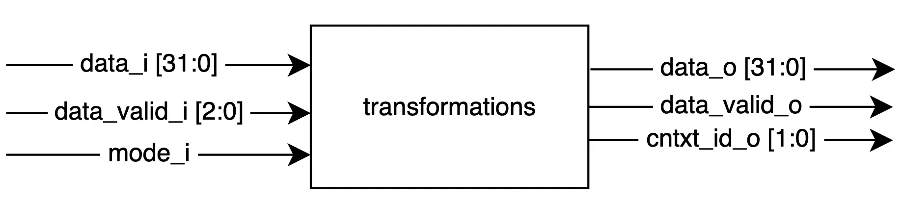
The input interface consists of 4 lanes, 8-bit wide each. Each lane on the input represents a unique channel of data The output interface on the other hand will have the same number of lanes, except all of the lanes will be time-shared by each of the 4 unique channels. Think of this as a row to column conversion in a matrix. The following diagram shows you this pictorially:
Loading the interactive workspace...