VIPT Cache Parameters
Figure out the cacheline size, sets and ways
Cache Design Parameters
The previous video discussed about the various parameters which lay the foundation of our cache design.
Parameters
| Parameter | Value |
|---|---|
| Size | 4KB |
| Cacheline Width | 4B (32b) |
| Page Size | 4KB |
| Ways | 4 |
| Logical Sets | 256 |
| SRAM Macro | sky130_sram_1kbyte_1rw1r_32x256_8 |
| SRAM Physical Sets | 256 |
| SRAM Data Width | 32 |
| Way Replacement Policy | Least Recently Used (LRU) |
Remember these parameters were decided in a way to ensure that this cache can be used as the Level 1 instruction cache for a RISC-V Processor. The RISC-V Processor supports 32b wide instructions which is same as the cacheline size for the VIPT cache.
Since the cache is virtually indexed and physically tagged - the Physical Address is also critical. The PA would be stored in the Tag RAMs and would be compared on cache look-up. The PA size is based on the minimum supported page size for the processor which in our case is fixed to 4KB.
Note: The size 4KB is actually the smallest available page size as per the RISC-V specifications. Using this and the fact that the physical address is 44b wide - the data RAMs would only need to store bits43:12 of the PA. This is because bits11:0 of the PA would be equal to bits11:0 of the VA as the page size is 4KB. As a result the Tag RAMs which store the PA would only need the 32b of information given by PA43:12.
Other important distinction to understand is the difference between logical sets and the physical sets. The SRAM macros size gives us the number of available physical sets in which the data needs to be arranged. In our case the SRAM macros have 256 sets with each set capable of storing 32b of information. The logical sets can be calculated by dividing the cache size with the number of ways and the cacheline size:
Logical Sets =  4 * 1024 * 8
               ---------------
                   4 * 32
If you do the above math, the number of logical sets would come out to be 256 as well. This matches the physical sets and hence it makes the cache architecture less complicated. Since the number of physical sets matches the number of logical sets - each SRAM macro would then represent the entire data stored for one single way for the data and the tag RAMs.
Cache Pipeline Overview
This lesson would cover the high-level cache microarchitecture as per the given interface pipeline. The cache architecture is pipelined into three stages as discussed below:
T0 Stage
- This stage provides the fetch valid along with the current VA and starts the cache access flow
T1 Stage
- In this stage the PA is available for the VA seen in T0 stage. It takes a cycle to get the PA for the flow
T2 Stage
- The final stage in the design where either the hit should be asserted along with the cache read data
- If the VA/PA missed in the cache then the miss request must be given out in this cycle and the stall must be asserted
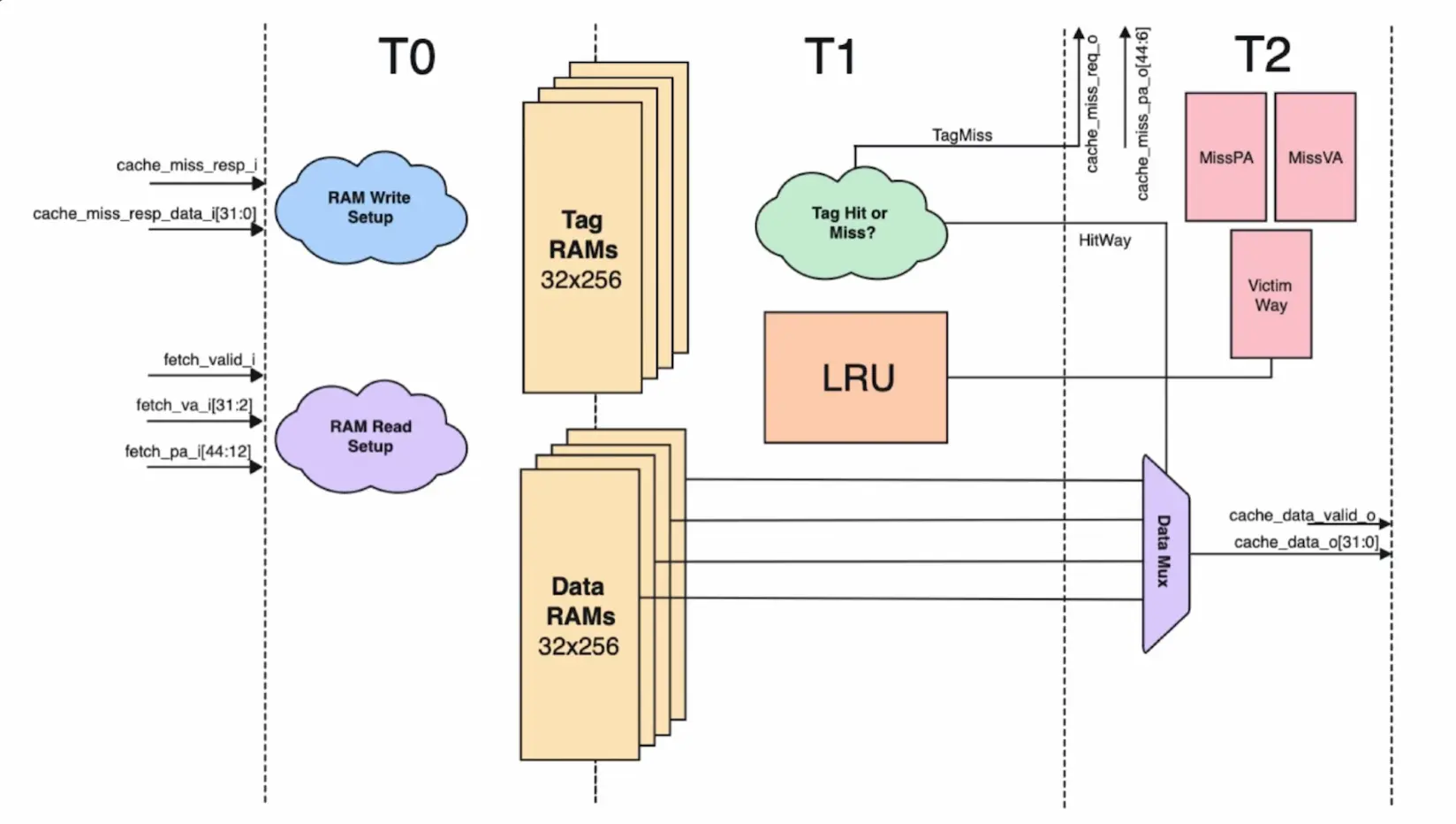
The above pipeline forms the base guidelines for our microarchitecture and depending on these stages we would see how the Tag and the Data Access Pipeline for the VIPT cache works along with the LRU replacement policy.
Loading the interactive workspace...