Setting Boundary
Find the frame: Mark, extract, and validate packets in a high-speed data stream!
DESCRIPTION:
In many high speed protocols like PCIe ,Ethernet etc, the structure of data at layers closer to the physical medium is quite different from the usual logical representation of data in terms of packets.
These standards define specific characters or codewords that form the fundamental structure of the protocol and allow the sender and receiver devices to handle various challenges and situations that arise due to the data being transferred over the physical medium.
Higher layer protocols that build upon these fundamental structures don’t care about any of the information carried by these character codewords. They work purely on the data bytes in the payload part of the character frames. Hence someone needs to demarcate the boundaries of these valid data packets to enable ease of operation at higher layers.
In this problem, we look at a simplified version of such a receiver module that has to parse an incoming stream of characters to identify boundaries of packets in the data.
PROBLEM STATEMENT:
You are working on a protocol that is built using 8-bit standard-defined characters. You need to identify and extract error free data packets by hunting for patterns in this stream.
Following are the characters defined in the protocol:
A -> 8’hA
B -> 8’hB
T -> 8’hF
D -> Data (could be anything except 8’hF)
You are required to hunt for the pattern AABA in the incoming stream of characters. Once found, all characters starting right after this pattern until a T character occurs form the data packet.
The following protocol is to be followed:
First and Last byte of data are to be marked by sop and eop output indications. Data bytes are marked by a 1’b1 in the data_o output indication (sop and eop bytes will also be data bytes). If you encounter a packet that is shorter than 4 Bytes of payload data, all of its data bytes shall be indicated by a 1’b1 in the err_o output indication (sop,eop,data indications, for errored bytes should be 1’b0)
As is usual with high speed processing designs, processing 1 character per cycle is a luxury that we do not have. Hence the input interface supplies 8-Bytes at a time.
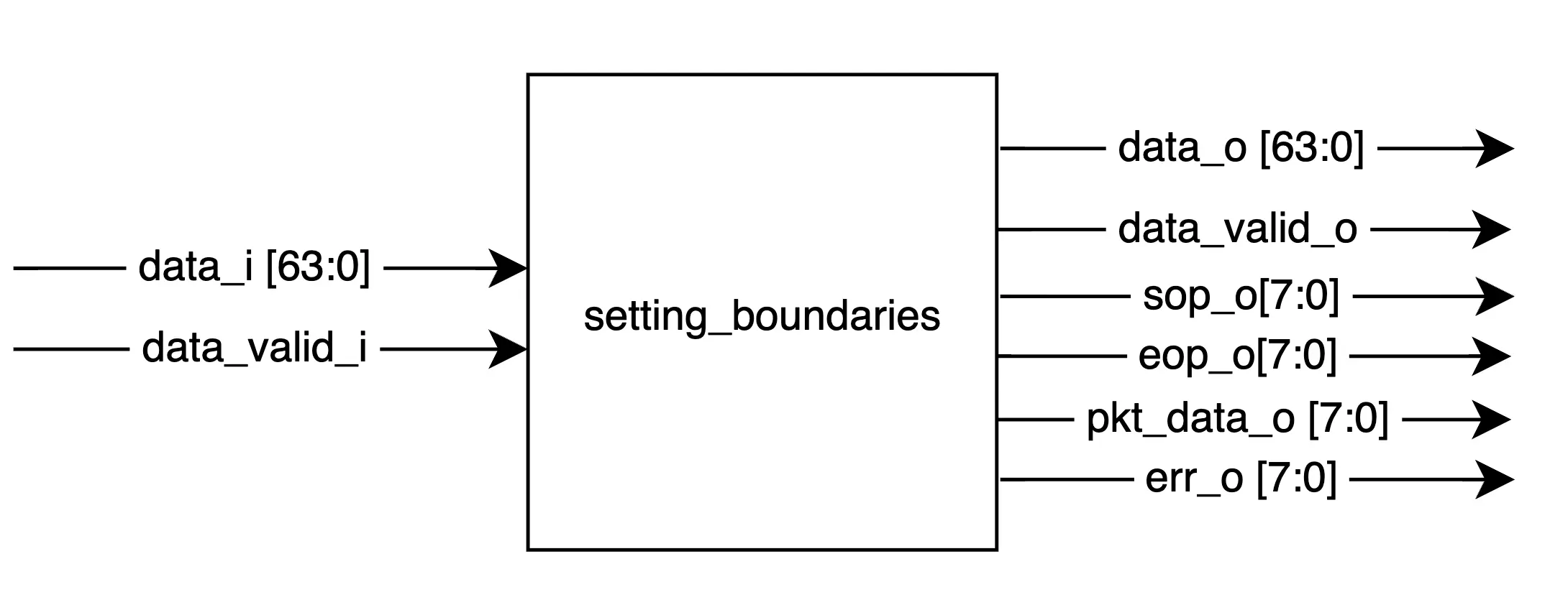
Interface Definition
The module consists of two interfaces
The input interface:
input [63:0] data_i     -> input data
input        data_val_i -> data valid indication
The output interface
output [63:0] data_o        -> output data bus
output        data_valid_o  -> data valid qualifier for output bus
output [7:0]  sop_o         -> start of packet indication. 1-bit per lane.
output [7:0]  eop_o         -> end of packet indication. 1-bit per lane.
output [7:0]  pkt_data_o    -> data marker. 1-bit per lane
output [7:0]  err_o         -> errored packet indication. 1-bit per lane
Interface Requirements: 1. Valid packet sizes can range from 4 to 16 bytes. This includes just the payload, framing bytes not counted. 2. Testbench ensures that the framing words are always present. I.e there will be no case of a missing terminating character etc.
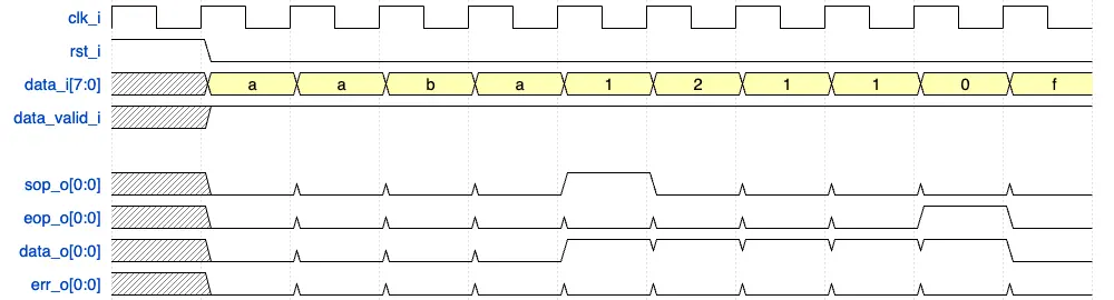
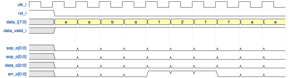
Interface Timing Diagram:
Below interface diagram explains the protocol assuming a 1 character (8-bit) input interface for ease of visualization. The same needs to be implemented with an 8 character interface in the problem.
Data packet:
Errored packet:
Related concepts
Loading the interactive workspace...